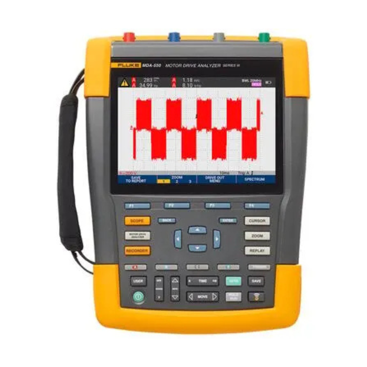
Fluke MDA-550 Series III Motor Drive Analyzer — Bangladesh's Most Advanced Tool for VFD Troubleshooting
In today's fast-moving industrial landscape, motor drive failures are one of the most costly and time-consuming problems an electrical engineer or maintenance technician can face. Diagnosing a faulty Variable Frequency Drive (VFD) or inverter system without the right tool can take hours — sometimes days. The Fluke MDA-550 Series III Motor Drive Analyzer completely changes that reality. This is not just another oscilloscope — it is a purpose-built, intelligent analyzer that guides you through every step of motor drive troubleshooting with speed, accuracy, and confidence.
Three Powerful Tools in One Device
The Fluke MDA-550 Series III is three powerful tools in one — a motor-drive analyzer, a waveform analyzer, and a recording data logger. For maintenance engineers and industrial electricians in Bangladesh working across RMG factories, power plants, manufacturing facilities, and commercial buildings, having three instruments combined into one portable unit is a massive advantage — both in terms of cost savings and field efficiency. If you're comparing options, take a look at our full range of oscilloscopes and waveform analyzers to see how the MDA-550 stacks up.
Guided Testing — No Guesswork, Ever
One of the most frustrating parts of motor drive troubleshooting is knowing where to start. The MDA-550 Series III eliminates that frustration entirely. Simply select a test and the step-by-step guided measurements show you exactly where to make voltage and current connections, while the preset measurement profiles ensure you capture all the data you need for each critical motor-drive section — from the input to the output, the DC bus, and the motor itself. Even a technician who is not a VFD specialist can operate this tool confidently on day one, as outlined in Fluke's official product documentation. For a deeper walkthrough of this workflow, see our guide on VFD and motor drive troubleshooting basics.
Measure Every Critical Parameter
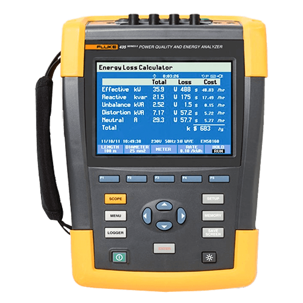
The Fluke MDA-550 Series III measures key motor-drive parameters including voltage, current, DC bus voltage level and AC ripple, voltage and current unbalance and harmonics, voltage modulation, and motor shaft voltage discharges. It can also perform extended harmonics measurements to identify the effects of low and high order harmonics on your electrical power system. This level of measurement depth means you can pinpoint exactly what is causing a motor drive problem — whether it is upstream power quality issues, drive output problems, or bearing currents damaging the motor itself. Engineers dealing specifically with power quality issues may also want to check our power quality analyzers lineup.
Built-In Report Generator — Document Everything On the Spot
For engineers working on client sites or managing regulatory compliance in Bangladesh's growing industrial sector, documentation is everything. The MDA-550 Series III features a built-in report generator that allows users to quickly and easily generate as-found and as-left reports. No more spreadsheets, no more manual notes — just a clean, professional report generated right from the device, ready to share with clients or management.
4 Channels, 500MHz — Industrial-Grade Performance
The MDA-550 Series III delivers 4-channel measurement capability at 500MHz bandwidth, giving you the resolution and speed needed to capture fast transient events, PWM switching signals, and shaft voltage discharge spikes that cheaper analyzers simply miss. When you are diagnosing intermittent motor failures or investigating bearing damage caused by shaft currents, this level of performance is non-negotiable.
Wi-Fi Connectivity and PC Software Included
The MDA-550 Series III comes complete with FlukeView-2 PC software and a Wi-Fi dongle, enabling wireless data transfer and advanced analysis on your computer. For engineering teams managing multiple sites across Bangladesh, this connectivity makes collaborative troubleshooting and centralized reporting effortless.
Who Needs the Fluke MDA-550 Series III in Bangladesh?
This is a professional-grade instrument for serious users:
- Industrial maintenance engineers managing VFD-driven systems in factories
- Electrical contractors servicing motor control centers and drives
- Power quality engineers investigating harmonic distortion issues
- Plant engineers at textile mills, cement plants, and steel factories
- Electrical safety auditors conducting compliance inspections
Browse our complete Fluke test and measurement tools range for other instruments that pair well with the MDA-550 in a full diagnostic toolkit.
Fluke MDA-550 Series III Price in Bangladesh
The Fluke MDA-550 Series III price in Bangladesh reflects its status as the world's leading motor drive analyzer — engineered in the USA by Fluke Corporation, the most trusted name in electrical testing. For any organization where motor drive downtime means production losses, this analyzer pays for itself with the very first breakdown it prevents. Check current pricing and availability on this page, or contact our sales team for a formal quotation and bulk order pricing.
Frequently Asked Questions
What is the Fluke MDA-550 Series III used for? It is used to troubleshoot and diagnose Variable Frequency Drive (VFD) and motor drive systems, combining a motor-drive analyzer, waveform analyzer, and data logger in a single portable device.
Can a technician without VFD expertise use this device? Yes. The guided, step-by-step testing feature shows exactly where to connect voltage and current probes and uses preset measurement profiles, making it accessible even for technicians new to VFD diagnostics.
What parameters can the MDA-550 Series III measure? It measures voltage, current, DC bus voltage and AC ripple, voltage and current unbalance, harmonics, voltage modulation, and motor shaft voltage discharges, along with extended harmonics analysis.
Does it support report generation for compliance documentation? Yes. It has a built-in report generator that produces as-found and as-left reports directly from the device, useful for client documentation and regulatory compliance.
What is the channel count and bandwidth of the MDA-550 Series III? It offers 4-channel measurement at 500MHz bandwidth, allowing it to capture fast transient events, PWM switching signals, and shaft voltage discharge spikes.
Does the MDA-550 Series III support wireless data transfer? Yes. It ships with a Wi-Fi dongle and FlukeView-2 PC software for wireless data transfer and advanced analysis on a computer.
Who typically buys this analyzer in Bangladesh? Industrial maintenance engineers, electrical contractors, power quality engineers, plant engineers at textile mills and cement/steel factories, and electrical safety auditors are the primary users.
How can I get the current price in Bangladesh? You can view pricing directly on this product page or contact our sales team
for a formal quotation and bulk order pricing.


 Calibration
 HVAC/Clean Rooms
 Electrical
 Temperature Meters
 Power & Energy
 Mechanical & Maintenance
 Pharma, Health & Biomedical
 Drone Solution
 Networking
 Transformer & Relay Testing
 Insulation, Resistance and Battery
 Fault Testing & Diagnostics
 Lightning Protection Solution
 Education, Research & Development
 Civil Equipment
 Renewable Energy
 Cleaning and supplies
 Power Tools
 Safety Tools
 Hardwares
 Construction Supply
 Stationeries
 Garden Tools
 Accessories
 Machines
 Hand Tools