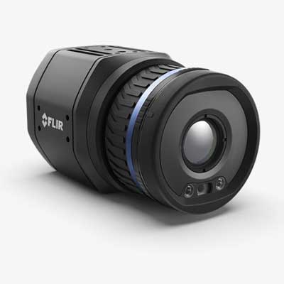
Specifications: FLIR Axxx-Series Smart Sensor
Digital I/O connector type
M12 12-pin A-coded, Male (shared with external power)
Digital Inputs
2x opto-isolated, Vin(low)= 0–1.5 V, Vin(high)= 3–25 V
Digital Output Purpose
• As a function of alarm, output to external device • Fault (NC)
Digital Outputs
3x opto-isolated, 0–48 V DC, max. 350 mA; solid-state opto relay; 1x dedicated as Fault output (NC)
Encoding
Video stream: H.264, MPEG4, or MJPEG Radiometric stream: Compressed JPEG-LS, FLIR radiometric
Ethernet Interface
Wired, Wi-Fi (optional)
WiFi
Optional feature purchased separately. RP-SMA, female connector
EMC
• ETSI EN 301 489-1 (radio) • ETSI EN 301 489-17 (radio) • EN 61000-4-8 (magnetic field) • FCC 47 CFR Part 15 Class B (emission US) • ISO 13766-1 (EMC - Earth-moving and building construction machinery) • EN ISO 14982 (EMC - Agricultural and forestry machinery)
Image Frequency
30 Hz
Thermal Sensitivity/NETD
Lens dependent
Accuracy
±2°C (±3.6°F) or ±2% of reading, for ambient temperature 15°C–35°C (59°F–95°F) and object temperature above 0°C (32°F)
Alarm Functions
On any selected measurement function, digital in, and internal camera temperature
Alarm Output
• Digital out • E-mail (SMTP) (push) • EtherNet/IP (pull) • File transfer (FTP) (push) • Modbus TCP master write (push) • Modbus TCP slave (pull) • MQTT (push) • Query over RESTful API (pull) • ONVIF • Store image or video
Communication & Data Storage
Digital I/O connector type
M12 12-pin A-coded, Male (shared with external power)
Digital I/O isolation voltage
500 VRMS
Digital input purpose
NUC, NUC disable, alarm
Digital Inputs
2x opto-isolated, Vin(low)= 0–1.5 V, Vin(high)= 3–25 V
Digital Output Purpose
• As a function of alarm, output to external device • Fault (NC)
Digital Outputs
3x opto-isolated, 0–48 V DC, max. 350 mA; solid-state opto relay; 1x dedicated as Fault output (NC)
Encoding
Video stream: H.264, MPEG4, or MJPEG Radiometric stream: Compressed JPEG-LS, FLIR radiometric
Ethernet
For control, result, image, and power
Ethernet Communication
TCP/IP socket-based FLIR proprietary
Ethernet Connector Type
M12 8-pin X-coded, female; RP-SMA, female
Ethernet Interface
Wired, Wi-Fi (optional)
Ethernet Power
Power over Ethernet, PoE IEEE 802.3af class 3
Ethernet Protocols
• EtherNet/IP • IEEE 1588 • Modbus TCP Master • Modbus TCP Slave • MQTT • SNMP • TCP, UDP, SNTP, RTSP, RTP, HTTP, HTTPS, ICMP, IGMP, sftp (server), FTP (client), SMTP, DHCP, MDNS (Bonjour), uPnP
Ethernet Standard
IEEE 802.3
Ethernet Type
1000 Mbps
Image Storage
Records up to 100 FLIR radiometric JPEG; storage as function of: alarm, scheduling, or user interaction (camera web)
Multicast
Yes
RS-232
NA
Video Storage
Records up to 10 H.264 videos; storage as function of alarm — 5 sec. before alarm and 5 sec. after alarm.
WiFi
Optional feature purchased separately. RP-SMA, female connector
Imaging & Optical
Available Lenses
6°, 24°, 14°, 42°, 2.0x Micro, Dual FOV (14° + 24°) athermalized lenses, 80°
Contrast Enhancement
FSX® / Histogram equalization (IR only)
Detector Pitch
17 µm
Focal Plane Array (FPA)
Uncooled microbolometer
Focus
One-shot contrast, motorized, and manual
Image Frequency
30 Hz
Image Source
Video stream 0: visual / IR / MSX® (visual camera is an optional feature) Video stream 1: visual Radiometric video stream: IR
IR Resolution
320 × 240
Multi-Streaming
Yes
Overlay
With / Without
Pixel Format
Video stream: YUV411 Radiometric stream: MONO 16
Radiometric IR video streaming
RTSP protocol
Readout
Measurement results: • Ethernet/IP (pull) • Modbus TCP master (push) • Modbus TCP slave (pull) • MQTT (push) • Query over REST API (pull) • Measurements and still image (radiometric JPEG, visual 640 × 480, visual 1280 × 960), read access only • Web interface
Spectral Range
7.5–14 µm
Streaming Resolution
Video stream 0: 640 × 480 pixels Video stream 1: 1280 × 960 pixels Radiometric stream: 320 × 240 pixels
Thermal Sensitivity/NETD
Lens dependent
Video Streaming
RTSP protocol
Visible Camera
Optional accessory; disabled when 80° lens in use
Measurement & Analysis
Accuracy
±2°C (±3.6°F) or ±2% of reading, for ambient temperature 15°C–35°C (59°F–95°F) and object temperature above 0°C (32°F)
Alarm Functions
On any selected measurement function, digital in, and internal camera temperature
Alarm Output
• Digital out • E-mail (SMTP) (push) • EtherNet/IP (pull) • File transfer (FTP) (push) • Modbus TCP master write (push) • Modbus TCP slave (pull) • MQTT (push) • Query over RESTful API (pull) • ONVIF • Store image or video
Atmospheric transmission correction
Based on inputs of distance, atmospheric temperature, and relative humidity
Automatic hot & cold detection
Max./min. temperature value and position shown within box
Measurement Corrections
Global object parameters; local parameters per analyze function
Measurement Presets
Yes
Measurement Tools
10 spotmeters, 10 boxes or mask polygons, 3 Deltas (difference any value/reference/external lock), 2 isotherms (above/below/interval), 2 iso-coverage, 1 reference temperature, 2 lines, 1 polyline
Object Temperature Range
-20°C to 120°C (-4°F to 248°F), 0°C to 650°C (32°F to 1202°F), 300°C to 1500°C (572°F to 3632°F)
General
Base Mounting
4× M4 on 4 sides
Housing material
Aluminium
Size (L x W x H)
123 × 77 × 77 mm (4.84 × 3.03 × 3.03 in)
Weight
0.82 kg (1.8 lb), camera only
Environmental & Certifications
Corrosion
• ISO 12944 C4 G or H • EN60068-2-11
EMC
• ETSI EN 301 489-1 (radio) • ETSI EN 301 489-17 (radio) • EN 61000-4-8 (magnetic field) • FCC 47 CFR Part 15 Class B (emission US) • ISO 13766-1 (EMC - Earth-moving and building construction machinery) • EN ISO 14982 (EMC - Agricultural and forestry machinery)
Encapsulation
IEC 60529, IP 54, IP66 with accessory
Humidity (Operating and Storage)
IEC 60068-2-30/24 hours, 95% relative humidity, 25°C–40°C (77°F–104°F)/2 cycles
ONVIF Conformance
Yes. ONVIF Profile S
Operating Tem
perature Range
-20°C to 50°C (–4°F to 122°F): • -20°C to 40°C (-4°F to 104°F) (in free air) • 40°C to 50°C (104°F to 122°F) (mounted on cooling plate accessory) Maximum camera case temperature: 65°C (149°F)
Radio Spectrum
• FCC 47 CFR Part 15 Class C (2.4 GHz band US) • FCC 47 CFR Part 15 Class E (5 GHz band US) • RSS-247 (2.4 GHz and 5 GHz band Canada) • ETSI EN 300 328 V2.1.1 (2.4 GHz band EU) • ETSI EN 301 893 V2.1.1 (5 GHz band EU)
Shock
IEC 60068-2-27, 25 g
Tripod Mounting
UNC ¼″-20 on 2 sides
Vibration
• IEC 60068-2-6, 0.15 mm at 10–58 Hz and 2 g at 58–500 Hz, sinusoidal • IEC 61373 Cat 1 (Railway)
Power
External Power Operation
24/48 V DC 8 W max
External Voltage
Allowed range 18–56 V DC
Power Connection
M12 12-pin A-coded, male (shared with Digital I/O)
Power Consumption
• 7.5 W at 24 V DC typical • 7.8 W at 48 V DC typical • 8.1 W at 48 V PoE typical


 Calibration
 HVAC/Clean Rooms
 Electrical
 Temperature Meters
 Power & Energy
 Mechanical & Maintenance
 Pharma, Health & Biomedical
 Drone Solution
 Networking
 Transformer & Relay Testing
 Insulation, Resistance and Battery
 Fault Testing & Diagnostics
 Lightning Protection Solution
 Education, Research & Development
 Civil Equipment
 Renewable Energy
 Cleaning and supplies
 Power Tools
 Safety Tools
 Hardwares
 Construction Supply
 Stationeries
 Garden Tools
 Accessories
 Machines
 Hand Tools