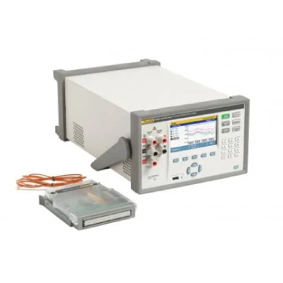
Product overview: Fluke 1586A Super-DAQ Precision Temperature Scanner
1586A Super-DAQ Precision Temperature Scanner
The 1586A Super-DAQ collects time-stamped precision temperature and electrical measurements for data analysis by technicians, engineers, and quality control personnel to verify process control, analyze interactive systems, ensure conformance to quality standards, or to correlate related events for R&D or troubleshooting. Measurement data and statistics can be viewed in tabular format for all active channels. With the graphing feature, up to four channels can be plotted at the same time, making it easy to quickly assess test setup and results before analyzing the data on a PC.
When configured with the DAQ-STAQ Multiplexer, the Super-DAQ has the accuracy of the best benchtop reference thermometer readouts for calibration of PRTs, RTDs, thermistors, or thermocouples. Lab efficiency can be increased when the Super-DAQ is connected to a Fluke Calibration drywell or bath and Automated Sensor Test routines are run.
The 1586 is ideal for a number of applications such as thermal mapping, temperature validation, process sensor calibration, and more. These applications are found in a various industries including pharmaceutical, biotechnology, food processing, aerospace, and automotive.
There are six key features that set the Super-DAQ apart from other products in its class:
- Best temperature measurement accuracy
- Flexible configuration for the factory or benchtop
- Multiple modes of operation
- Real-time graphing in color
- Data portability and security
- Automated sensor calibration
1. Best temperature measurement accuracy
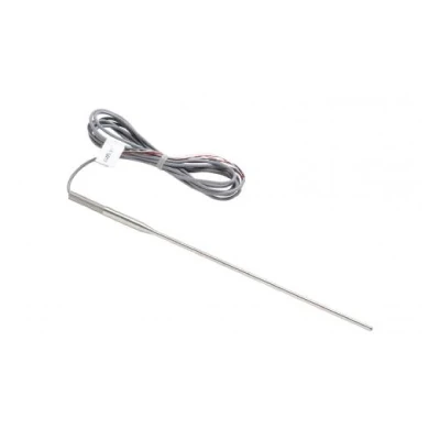
The 1586A Super-DAQ reads PRTs, thermocouples, and thermistors with best-in-class accuracy:
- PRTs ±0.005 °C (using external DAQ-STAQ Multiplexer)
- Thermocouples: ±0.5 °C (using High-Capacity Module and internal CJC)
- Thermistors: ±0.002 °C
2. Flexible configuration for the factory or benchtop
For factory applications, the Super-DAQ is configured with the internal High-Capacity Module. Connecting thermocouples or RTDs to input terminals can be time consuming—especially if you're using many sensors of the same type for one job, and then switching to a different sensor type for another job. The internal High-Capacity Module allows you to pre-configure multiple input modules and simply exchange one module for another, depending on your test requirements. Recall a stored test setup to make the changeover even faster. And if you prefer, you can always measure a variety of different input types at the same time in a single High-Capacity Module, including thermocouples, RTDs, voltage, resistance, or current.
For a calibration lab where accuracy is of primary importance, the Super-DAQ is best configured with a DAQ-STAQ Multiplexer. The external DAQ-STAQ features mini-jack thermocouple terminals—each with its own reference junction sensor—and patented mini-DWF, gold-plated input terminals, which accept bare wire, spade lug, or mini-banana-plug terminations. Easily connect and disconnect PRTs, thermistors, and thermocouples for benchtop temperature calibration. It can be stacked on the 1586 to reduce footprint in busy labs. Flexibility to configure the Super-DAQ for factory or calibration lab use reduces your equipment needs and cost.
3. Multiple modes of operation
The Super-DAQ can operate in four modes that let you scan, monitor, measure, or function as a digital multimeter from a single instrument. Sequentially scan through channels based on a user defined test. Monitor any single channel during a scan, without interrupting the scan. Measure and record data on a single channel without the need of a pre-configured test file. Or in DMM mode, use the front panel channel like a familiar benchtop digital multimeter to quickly measure dc voltage, dc current, or 2-wire and 4-wire resistance without the need to configure the channel.
4. Real-time graphing in color
Most data acquisition systems only let you view data on one channel. But now the Super-DAQ, lets you view real time data for all channels in table format, or you can chart up to four channels in color at the same time. You can zoom in or out to see data of interest and monitor trends. A history mode lets you scroll through collected data within a scan file—all without a PC and expensive charting programs. Switch between chart view and table view of various measurement data and statistics
5. Data portability and security
The Super-DAQ includes 20 MB internal memory that can store over 75,000 time-stamped readings. Data and set-up files can be easily moved to a PC for analysis using a USB flash drive or over a network using the LAN interface connection. The Super-DAQ also includes two levels of data security to prevent unauthorized users from tampering with or forging test data or setup files. This security feature is especially important to industries that are regulated by government agencies where data traceability is required.
6. Automated sensor calibration
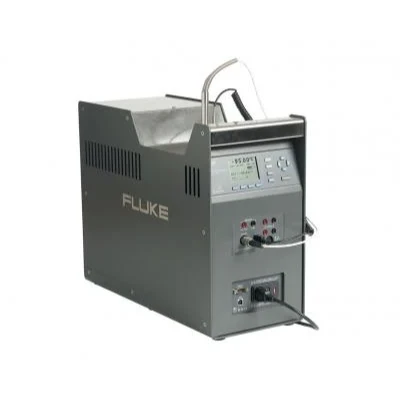
With the Automated Test feature, you can automate sensor calibration without a PC and software. When connected to a Fluke Calibration drywell or fluid bath via the RS-232 interface, the Super-DAQ takes control of the temperature source and runs your calibration automatically. You simply program the number of setpoint temperatures and their values, select a scan sequence (linear, alternate, up/down), assign a reference channel, and set the required stability band. The Super-DAQ monitors the temperature source's stability via the reference channel, collects the data once stabilized, and then advances to the next setpoint temperature. After you configure and start the test, you can walk away to work on other things. The Super-DAQ just made your day a whole lot easier.


 Calibration
 HVAC/Clean Rooms
 Electrical
 Temperature Meters
 Power & Energy
 Mechanical & Maintenance
 Pharma, Health & Biomedical
 Drone Solution
 Networking
 Transformer & Relay Testing
 Insulation, Resistance and Battery
 Fault Testing & Diagnostics
 Lightning Protection Solution
 Education, Research & Development
 Civil Equipment
 Renewable Energy
 Cleaning and supplies
 Power Tools
 Safety Tools
 Hardwares
 Construction Supply
 Stationeries
 Garden Tools
 Accessories
 Machines
 Hand Tools