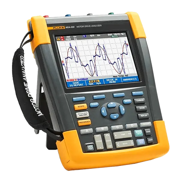
Model: Fluke MDA-510 and MDA-550 Motor Drive Analyzers
The Fluke MDA 510 and MDA 550 Motor-Drive Analyzers retain period and eliminate the annoyance of setting going on puzzling measurements, even though simplifying the troubleshooting process for modifiable frequency drives.
Simply choose a test and the step-by-step guided measurements function you where to make voltage and current links, even though the preset measurement profiles ensure you will occupy the entire single one the data you dependence for each vital motor-objective section from the input to the output, the DC bus, and the motor itself.
From basic to objector measurements, the MDA-500 Series has you covered and bearing in mind a built-in excuse generator you can speedily and easily generate as-found, and as-left reports taking into account confidence.
Keep here your confidence the great Fluke product you are receiving If you want to Buy this product check at Tools Bangladesh.
Key features: Fluke MDA-510 and MDA-550 Motor Drive Analyzers
- Guided testing with graphical step-by-step voltage and current connection diagrams makes setup and connection to variable frequency drives easier than ever
- Preset measurement profiles collect data based on the chosen test procedure and reduce the need for complex configuration
- Built-in report writing capabilities make it easy to produce professional as-found and as-left motor-drive troubleshooting reports
Specifications: Fluke MDA-510 and MDA-550 Motor Drive Analyzers
| Measurement Function |
| DC voltage (V dc) |
| Maximum voltage with 10:1 or 100:1 probe |
1000 V |
| Maximum resolution with 10:1 or 100:1 probe |
1 mV |
| Full scale reading |
999 counts |
| Accuracy at 4 s to 10 us/div |
±(3 % + 6 counts) |
| AC voltage (V ac) |
| Maximum voltage with 10:1 or 100:1 probe |
1000 V |
| Maximum resolution with 10:1 or 100:1 probe |
1 mV |
| Full scale reading |
999 counts |
| 50 Hz |
±(3 % + 10 counts) - 0.6 % |
| 60 Hz |
±(3 % + 10 counts) - 0.4 % |
| 60 Hz to 20 kHz |
±(4 % + 15 counts) |
| 20 kHz to 1 MHz |
±(6 % + 20 counts) |
| 1 MHz to 25 MHz |
±(10 % + 20 counts) |
| True-rms voltage (V ac+dc) |
| Maximum voltage with 10:1 or 100:1 probe |
1000 V |
| Maximum resolution with 10:1 or 100:1 probe |
1 mV |
| Full scale reading |
1100 counts |
| DC to 60 Hz |
±(3 % + 10 counts) |
| 60 Hz to 20 kHz |
±(4 % + 15 counts) |
| 20 kHz to 1 MHz |
±(6 % + 20 counts) |
| 1 MHz to 25 MHz |
±(10 % + 20 counts) |
| PWM voltage (V pwm) |
| Purpose |
To measure on pulse width modulated signals, like motor drive inverter outputs |
| Principle |
Readings show the effective voltage based on the average value of samples over a whole number of periods of the fundamental frequency |
| Accuracy |
As Vac+dc for sinewave signals |
| Peak voltage (V peak) |
| Modes |
Max peak, min peak, or pk-to-pk |
| Maximum voltage with 10:1 or 100:1 probe |
1000 V |
| Maximum resolution with 10:1 or 100:1 probe |
10 mV |
| Accuracy |
| Max peak, min peak |
±0.2 division |
| Pk-to-pk |
±0.4 division |
| Full scale reading |
800 counts |
| General Specification |
| Current (AMP) with current clamp |
| Ranges |
Same as V ac, Vac+dc or V peak |
| Scale Factors |
0.1 mV/A, 1 mV/A, 10 mV/A, 20 mV/A, 50mV/A, 100 mV/A, 200 mV/A, 400 mV/A |
| Accuracy |
Same as Vac, Vac+dc or V peak (add current clamp accuracy) |
| Frequency (Hz) |
| Range |
1.000 Hz to 500 MHz |
| Full scale reading |
999 counts |
| Accuracy |
±(0.5 % + 2 counts) |
| Voltage/Herz ratio (V/Hz) |
| Purpose |
To show the measured V PWM value (see V PWM) divided by the fundamental frequency on variable ac motor speed drives |
| Accuracy |
% Vrms + % Hz |
| Voltage unbalance drive input |
| Purpose |
To show the highest percentage difference of one of the phase vs average of the 3 true-rms voltages |
| Accuracy |
Indicative percentage based on Vac+dc values |
| Voltage unbalance drive output and motor input |
| Purpose |
To show the highest percentage difference of one of the phase vs average of the 3 PWM voltages |
| Accuracy |
Indicative percentage based on V PWM values |
| Current unbalance drive input |
| Purpose |
To show the highest percentage difference of one of the phase vs average of the 3 AC current values |
| Accuracy |
Indicative percentage based on Aac+dc values |
| Current unbalance drive output and motor input |
| Purpose |
To show the highest percentage difference of one of the phase vs average of the 3 AC current values |
| Accuracy |
Indicative percentage based on A ac values |
| Rise and fall time |
| Readings |
Voltage difference (dV), time difference (dt), voltage vs time difference (dV/dt), overshoot |
| Accuracy |
As oscilloscope accuracy |
| Harmonics and spectrum |
| Harmonics |
DC to 51st |
| Spectrum ranges |
1…9 kHz, 9-150 kHz (20 MHz filter on), up to 500 MHz (voltage modulation) |
| Shaft voltage |
| Events / second |
Indicative percentage based on rise and fall time (Impulse discharges) measurements |
| Report data capture |
| Number of screens |
Typical 50 screens can be saved in reports (depends on compression ratio) |
| Transfer to PC |
Using 2 GB USB stick or mini-USB to USB cable and FlukeView™ 2 for ScopeMeter™ test tool |
| Probe settings |
| Voltage probe |
1:1, 10:1, 100:1, 1000:1, 20:1, 200:1 |
| Current clamp |
0.1 mV/A, 1 mV/A, 10 mV/A, 20 mV/A, 50 mV/A, 100 mV/A, 200 mV/A, 400 mV/A |
| Shaft voltage probe |
1:1, 10:1, 100:1 |
Includes: Fluke MDA-510 and MDA-550 Motor Drive Analyzers
- 1x BP 291 li-ion battery pack
- 1x BC190 charger/power adapter
- 3x VPS 100:1 high voltage probes with alligator clips
- 1x VPS410-II-R 10:1 500MHz voltage probe
- 3x i400s ac current clamp
- 1x C1740 carrying case
- 1x 2 GB USB drive with manuals and FlukeView™ 2 software
- 1x SVS-500 shaft voltage set (3x brush, probe holder, two-piece extension rod and magnetic base)
Accessories: Fluke MDA-510 and MDA-550 Motor Drive Analyzers
- Kits
- Automotive
- Adapters
- Batteries
- Connectors
- Cases
- Clips
- Other
- Fluke calibration software
- Probes
- Test leads
- Cables
- Test probes































 Calibration
 HVAC/Clean Rooms
 Electrical
 Temperature Meters
 Power & Energy
 Mechanical & Maintenance
 Pharma, Health & Biomedical
 Drone Solution
 Networking
 Transformer & Relay Testing
 Insulation, Resistance and Battery
 Fault Testing & Diagnostics
 Lightning Protection Solution
 Education, Research & Development
 Civil Equipment
 Renewable Energy
 Cleaning and supplies
 Power Tools
 Safety Tools
 Hardwares
 Construction Supply
 Precision Tools
 Garden Tools
 Accessories
 Machines
 Hand Tools